| Science & Non-profit | ||
A telescopic method for photographing within 8x8 cm minirhizotrons.
| Keywords
Endoscope, Minirhizotron, Root study methods, Root growth, Root distribution. AbstractA system for photographing within 8x8 cm minirhizotrons is described, that uses a telescopic lens instead of an endoscope. A comparison was made between the telescope system and the commonly used endoscope system. Photographs obtained with the telescope system are of superior quality as compared to those of the endoscope system, without a decrease in the field of view. Photographs obtained by the telescope system can easily be aligned in a sequence that shows the entire length of the minirhizotron wall as a single image. Furthermore, the telescope system is portable, shockproof, cheap, easily repaired, and can be operated by a single person. by:Geert Poelman, Johan van de Koppel and Gerard Brouwer. PublishedPlant and Soil 185: 163-167, 1996. |
Introduction
The study of root systems is an important field of research in plant ecology. For instance, it is well known that roots play a vital role in the ability of plants to obtain soil water and nutrients. Therefore, they determine to a large extent the competitive abilities of a plant species (see, e.g., Grime et al. 1991). Also, root turnover and root decomposition play a major role in the carbon and nutrient dynamics of ecosystems (Vogt et al. 1986). However, root systems are also among the most neglected fields of research in ecology, mostly due to practical difficulties.
A common approach to studying root dynamics in natural systems is sequential core sampling of root mass (Böhm 1979). However, the destructive nature of this method limits its appli-cation as repeated measurement of the same set of roots is impossible. A non-destructive method for studying root systems is available in the form of the minirhizotron system (Bates 1937, Wadding-ton 1971, Vos and Groenwold 1983, Brown and Upchurch 1987, McMichael and Taylor 1987). The minirhizotron system basically consists of a transparent observation tube (the actual minirhizotron) permanently inserted into the soil and equipment that enables objects behind the wall of the tube to be observed.
Several systems for observing roots growing onto the minirhizotron walls are in use: an endoscope system, a system that uses a video camera, and combinations of both (Sanders and Brown 1978, Gregory 1979, Vos and Groenwold 1983, Upchurch and Ritchie 1983). These systems do, however, have some substantial limitations. Both systems are fragile, very expensive (Taylor 1987), and have long repair times in case of malfunction. The video system is bulky, which restricts the operators movements. These limitations make it less suited for ecological studies that are performed under field conditions. Furthermore, the quality and shape of the pictures produced are far from ideal. Ideally one would want to obtain a single high quality image showing the entire minirhizotron wall. In reality though, the pictures produced are circular, slightly deformed fragments of the total image. Consequently, they cannot easily be aligned to show the entire minirhizotron wall as a single image.
This article describes a telescope system that suffers from none of the aforementioned limitations. It's design is based on a mirror and a camera fitted with a telescopic lens. Furthermore, a simple mechanical method is included for automatically registering the object's depth within the minirhizotron. For comparison, photographs made with both the telescope system and the endoscope system described by Vos and Groenwold (1983) are presented.
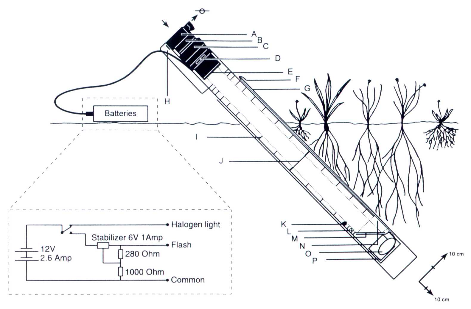
Figure 1. Complete telescope system set-up, including electronic schematics of the battery, and the improvements proposed in the discussion. The dotted line represents the outer light trajectory from the object to the camera. A = camera body, B = 2x extender, C = 300mm lens, D = Aperture in frame and PVC entrance block for focusing, E = UV-filter, F = Lead of tape-measure that is anchored to the minirhizotron, G = Minirhizotron wall, H = camera fastening screw, I = diaphragm, J = Polaroid filter, K = flashtube with a Polaroid filter at a 90 degree angle, L = halogen light, M = optical mirror at a 45 degree angle, N = viewing aperture, O = spring powered tape-measure, P = flash electronics.
Description of the telescope system
The system described in this article basically consists of a long tubular frame with a mirror at a 45° angle at one end and a camera with a telescopic lens at the other end (see fig.1). The frame consists of a square 1 mm thick stainless steel tube of 76x76x1547 mm that is constructed out of two "L" shaped halves held together by screws. In the front end we suggest a "U" shaped piece to fasten the camera onto the frame. This piece consists of two square 15x15 mm tubes welded onto a middle plate at one end and onto the bottom of the frame at the other end.
Photographs are made using a high quality camera (Minolta 7000, Minolta co. ltd. 3-13-2-Chome, Azuchi-Machi, Chou-Ku, Osaka 541, Japan) fitted with a 300 mm lens (Sigma 70-300 mm F4-5,6 apo macro, Sigma co. 2-3-15 Iwato-Minami Komae-Shi, Tokyo 201, Japan), a 2X extender (Soligor C/D7 AF 2X extender, P.O. box 100111, D-70745 Leinfelden-E, Germany) and a UV filter (Astron 58 mm UV, Benel b.v., Voltastraat 2, 7903 AB, Hoogeveen, Netherlands). The focusing ring of the lens slides into a square section of polyvinylchloride with a circular hole in its centre, placed at the entrance of the frame. Holes are made alongside the frame and through this lens-holder, to enable focusing. Photo-graphs are made through a rectangular aperture at the back end of the frame, in front of the mirror. This aperture stretches over the width of the frame and has a diameter of 53 mm.
Directly underneath this aperture a piece of stainless steel is placed at a 45° angle to the frame on which the mirror (73x76 mm) is attached (on the glass side) with double-sided, all-weather, thick foamy tape. It is imperative to use an optical mirror (Van Doornen innovision, Zuidplasstraat 1, 2751 GL Moerkapelle, The Netherlands) to prevent the appearance of ghost images. The piece of stainless steel only stretches for the 76 mm width of the mirror. The distance between the film and the object is 1645 mm.
Filtering out flash reflections
The system uses two Polaroid filters at a 90° angle to block out direct reflections of the flash on the minirhizotron wall. Both filters are simple pieces of Polaroid plastic (Hama 4824, 8855 Manheim, Germany). The first is attached to the flash and polarises the light, while the second can be placed at any site inside the frame as long as it does not obscure the image. To get a more even lighting of the object we frosted the first Polaroid filter on the flash tube side with sandpaper. Note that every filter halves the intensity of the light passing through.
Along the tube there are many diaphragms installed that block out internal reflections which would otherwise cause the image to blur. The diaphragms are made of a thin sheet of polyvinylchloride and are strengthened with supporting struts. Those diaphragms that are nearest to the mirror are omitted. Instead, the last part of the frame's inner side walls is covered with crepe paper. The entire inside of the system is painted flat black (XF-1, Tamiya plastic model co, 628, Oshika, Shizuoka-Citty, Japan). A computer program that calculates the number of diaphragms needed as well as their precise shape, can be obtained upon request.
Automatically including the object's position on the photographs
The system includes the position of the objects on the photo-graphs by extending a spring powered tape measure (Y 612CMG, Lufkin Europa B.V., P.O. Box 53, 7800 AB Emmen, The Netherlands) over the side of the image (see fig. 1). The body of the tape measure is situated behind the mirror and next to the flash electronics, on one of the system's inner sidewalls, while its lead is anchored to the top of the minirhizotron tube. Thus, the deeper the object is in the minirhizotron, the more the tape measure is extended.
 |
 |
|
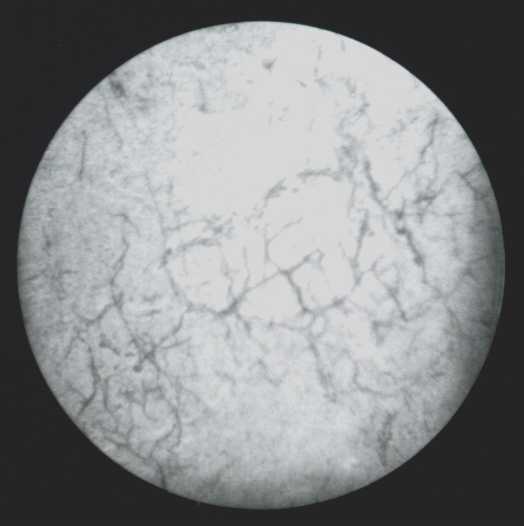
Figure 2. Comparison photographs. A = with an endoscope system, and B with the telescope system.
Results
Photographs taken by both systems at the same position in a minirhizotron are presented in figure 2. The resolution of the photographs obtained by the telescope system are superior to the resolution of photographs obtained with the endoscope system. The increase of resolution did not lead to a decrease of the field of view. (33.0 cm2 for the telescope system as compared to 28 cm2 for the endoscope system). furthermore, the pictures produced by the endoscope system are circular while those of the telescope system are rectangular. This allows the pictures to be aligned in a sequence that shows the entire minirhizotron as a single image. The round shape in contrast, as produced by the endoscope system, makes such an alignment virtually impossible. Furthermore, the photographs made using the endoscope system have a slight fish eye distortion while the photographs made with telescope system have not.
Discussion
The strength of the telescope system is its simplicity. All parts used can either be bought off the shelf or else are cheap enough for spares to be kept. As a consequence the telescope system can be repaired very quickly. The endoscope system, in contrast, may require many months for repair, which can seriously jeopardise any research project.
The telescope system is extremely rugged, provided one carries the camera and lenses separately, is able to withstand severe punishment. During our two-year study, the system required virtually no maintenance. Although not optimized for low weight, the system without camera and batteries only weighs approximately 6 kilogram. When using a small backpack, the system can be both carried and operated by a single individual.
The system has a few inherent limitations. The length of the observation tubes is limited to approximately 140 cm when using a 600 mm telelens. When the distance between the camera and the mirror is increased further, a more powerful lens must be used or else the image will only partly cover the photograph. The use of polaroid filters in order to stop reflection causes the system to be rather light inefficient. When the system is used for sampling inflatable minirhizotron systems (Gijsman et al 1991), the polaroid filters can be omitted, as their are no reflective inner surfaces. The use of a flash may not be essential in this case.
Our prototype can still be improved. We placed the flash tube almost directly underneath the image. This causes an uneven lighting of the image by the flash tube while the lighting provided by the halogen light, that is placed slightly further from the image, is even. Furthermore, the image width we used in our calculations is 80 mm while the system is in fact limited by the 73 mm width of the mirror. Thus the camera should have been placed closer to the image as this would have produced more detailed pictures and no black edges (91 mm closer taking no account of the safety margin used by some film developers). Another possible improvement to our telescope system is to use the manual version of the lens instead of the auto-focus version we used as this should now be available. Finally, using light-weight material for the construction of the frame will make transportation easier. Despite these possible improvements the telescope system has already proven to be a convenient tool for photographing roots growing onto minirhizotron walls, thus enabling non-destructive sequential observations of root systems in ecological studies.
Acknowledgements
We thank Rien Aerts, Jelte van Andel, Jan Bakker, Jacob Hogendorf, Frits Meiboom, and Odilia Velterop for their encouragement, support, and helpful criticism on this manuscript, and last but not least Wim Beukema and Ebel Top for their valuable technical assistance.
References